Important Information
Gridding Guidelines Document, All Configurations
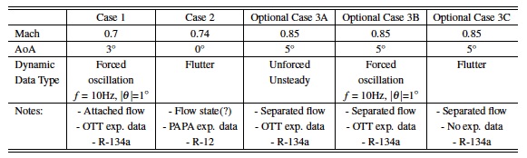
AePW-2 Test cases
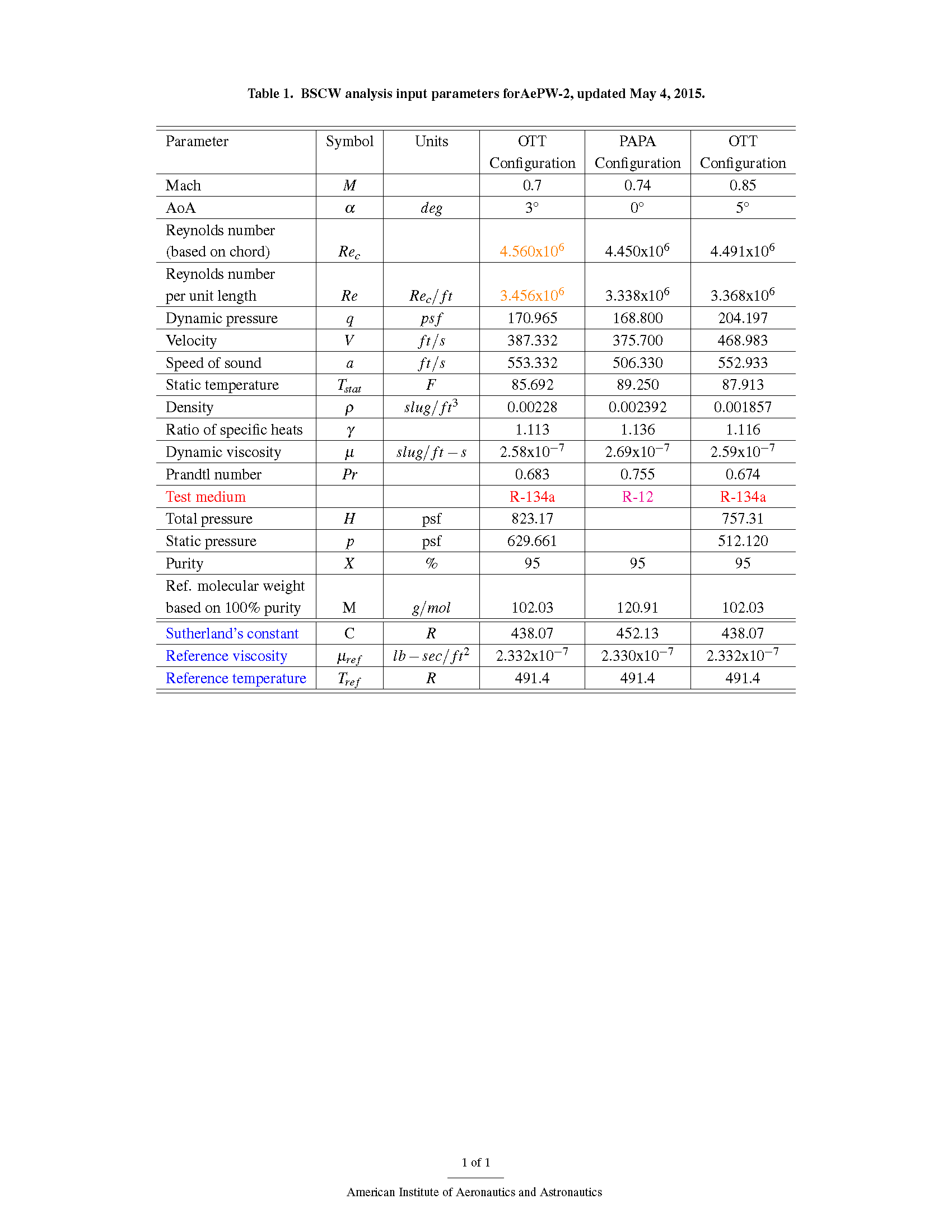
Analysis Parameters
Update log:
- 5/4/2015: Reynolds number for case 1 corrected
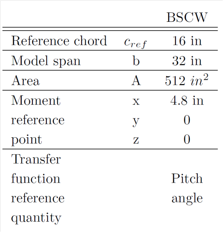
Reference Quantities
Geometry
BSCW Iges file: download
Grids
Grids provided by the organizing committee
Mixed Element Unstructured Grids generated using VGRID software
| Element | Resolution | Node or Cell based | |
|---|---|---|---|
| Unstructured | Tets and Mixed Element | Coarse/Medium/Fine | Node Based and Cell-Centered |
These grids were constructed using VGRID software from NASA Langley. The grids designed for node based (labeled 'nc') and cell-centered solvers are supplied. Grids with mixed elements (labeled 'mixed') and tetrahedral elements (labeled 'tets') are supplied.
Each mixed elements tar-file contains grid in aflr3 .ugrid format and the corresponding .cgns file. Each tetrahedral elements tar-file contains grid in native VGRID format (.cogsg, .bs, .mapbc) and the corresponding .cgns file.
Some files were too large and had to be split into parts. To combine the parts, use cat filename_part1 filename_part2 > filename.
Grids are in units of 'inch'. Information about grids, that is number of nodes, elements, etc., is provided in AePW_BSCW_Grid_Statistics_VGRID_Final.docx
Please report any issues with these grids to the Official AePW-2 email address.
Files
| Name | Size | Download | Download mapped mode shapes |
|---|---|---|---|
| Coarse tetrahedral node based | 324.3 MB | download | download |
| Coarse Mixed node based | 240.9 MB | download | download |
| Coarse tetrahedral cell-centered | 141.4 MB | download | download |
| Coarse Mixed cell-centered | 102.1 MB | download | download |
| Medium tetrahedral node based | 1015.5 MB | download | download |
| Medium Mixed node based | 789.6 MB | download | download |
| Medium tetrahedral cell-centered | 440.3 MB | download | download |
| Medium Mixed cell-centered | 331.5 MB | download | download |
| Part1: Fine tetradedral node based | 1.9 GB | download | download |
| Part2: Fine tetradedral node based | 1.3 GB | download | download |
| Part1: Fine Mixed node based | 1.5 GB | download | download |
| Part2: Fine Mixed node based | 1.1 GB | download | download |
| Fine tetrahedral cell-centered | 1.3 GB | download | download |
| Fine Mixed cell-centered | 1.0 GB | download | download |
| Grid Information | 121.3 KB | download | download |
Multi-block Structured Grids in Plot3D format
| Element | Resolution | Node or Cell based | |
|---|---|---|---|
| Structured | Multi-Block Structured | Coarse/Medium/Fine |
Three grids: coarse, medium, and fine in Plot3d format.
Files
| Name | Size | Download | Download mapped mode shapes |
|---|---|---|---|
| Coarse/Medium/Fine Multiblock structured grids in Plot3d Format | 571.6 MB | download | download |
| Neutral Map Files for Coarse/Medium/Fine grids | 20.0 KB | download | download |
Structural Dynamics Finite Element Model
A finite element model (FEM) in MSC Nastran has been generated to emulate the structural dynamics of the BSCW mounted on the PAPA system. The model was based on the structural dynamic properties reported previously. The FEM consists of a nearly rigid flat plate of the same planform dimensions as the PAPA wing, connected to a fixed point with two simulated springs at the axis of pitch rotation, as shown in the cartoon below. The axis of rotation is located at the same point at the axis of rotation for the PAPA flutter test, 8 inches from the leading edge, at the 50% chord. Fifteen grid points, form 8 CQUAD elements that are each 1 inch thick made of an invented light and stiff material. The structural grid points are laid out in a matrix: 3 chord-wise grid points; 5 span-wise grid points. Grid point 2 is located at the wing root at the axis of rotation and is constrained in 4 degrees of freedom, allowing only movement in the vertical translation and pitch rotation directions. i.e. it is constrained in the following degrees of freedom: translation in the flow-wise and span-wise directions, rotation in the yaw and roll directions, (i.e. degrees of freedom 1,2,4 and 6).
The overall mass properties and the spring constants values were specified to match the values defined in the experimental data report. The plunge spring stiffness was set to 219.75 slinch/s^2; the pitch spring stiffness was set to 35568.slinch-in^2/s^2/rad. The mass properties were established using concentrated masses at each of the grid points and a concentrated inertia at grid point 2. The distribution of the concentrated masses was generated to match the wing total mass, the wing total pitch inertia and place the center of gravity to correspond with the pitch rotational axis at the chord-wise center. From the experimental data report, the mass of the wing is 6.0237 slugs or 0.502 slinches; the pitch inertia is 2.777 slug-ft2 or 33.324 slinch-in2. Normal modes analysis of the FEM shows that the overall mass properties and the frequencies of the plunge and pitch mode match the measured values. The plunge mode has a frequency of 3.33 Hz; the pitch mode has a frequency of 5.20 Hz.
The plunge and pitch modes of the system are shown in plots below. Three levels of structural model are available for workshop participants: a detailed FEM, the FEM-extracted modal definition, and the mode shapes interpolated onto the provided grids. In addition, the organizing committee can interpolate the mode shapes onto additional grids, if requested, eliminating a possible source of differences among the solutions.
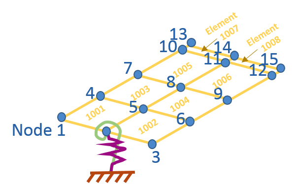
Finite element model diagram
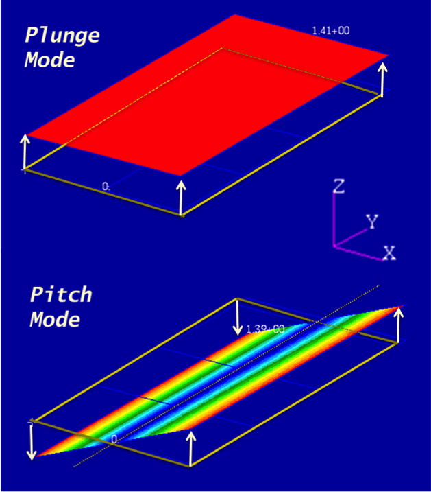
FEM modes diagram
MSC NASTRAN Finite element model (bulk data file)
| Name | Size | Download |
|---|---|---|
| BSCW_Faux_DistribMass_Dec2014JH.bdf | 4 Kb | download |
Modal structural model: (frequencies, mode shapes at structural node points)
| Name | Size | Download |
|---|---|---|
| BSCW_Faux_DistribMass_Dec2014JH.pch | 7 Kb | download |
| BSCW_Faux_DistribMass_Dec2014JH.f06 | 95 Kb | download |
Sensor Locations
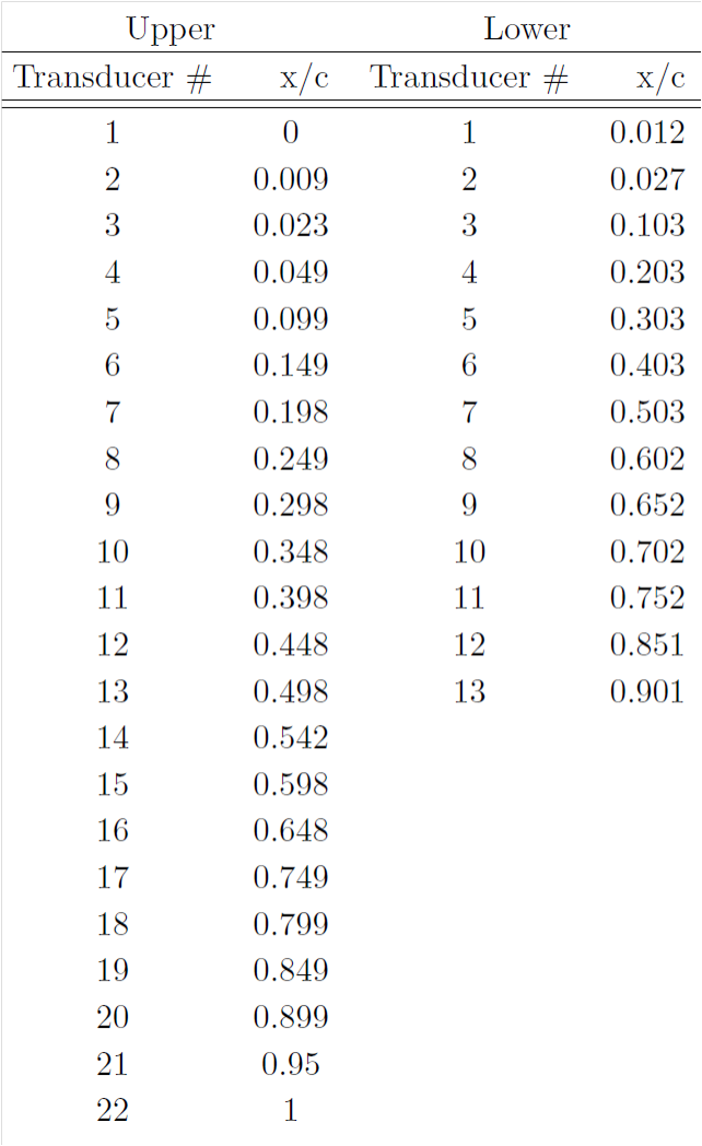
BSCW Sensor Locations
Publications and Presentations
BSCW summary presentation from the AePW-1
OTT testing of the BSCW, by Piatak and Cleckner
NASA_TM4457_BSCW.pdf Includes the physical properties of BSCW (includes measured coordinates in tables)
Testing of the BSCW splitter plate
NASA_TM104180_BMP.pdf Benchmark Models Program description and highlights
AIAA-1992-2368_Dansberry.pdf Includes description of the dynamic characteristics of the BSCW
AePW-1 BSCW Workshop presentations
RUAG_BSCWBSCW_Schuster
BSCW_Mavriplis
BSCW_MSmith
BSCW_ANSYS
BSCW_Chwalowski