Benchmark Super Critical Wing Home
Analysts Information
Information necessary to analyze this configuration:
Experimental Data
Wind tunnel tests were conducted at NASA Transonic Dynamics Tunnel of the Benchmark Supercritical Wing as part of the checkout of the Oscillating TurnTable (OTT); TDT Test 548, August 2000, conducted by Dave Piatak et al. Original testing of this model was performed under the Benchmark Models Program using a Pitch and Plunge Apparatus (PAPA) mounting system; TDT Test 470, 1992, by Bennett et al; performed testing in both in Air and R-12 test media.
Results from AePW-1
The results generated by the analysis teams are described and assembled into a MATLAB database. These results are compared with the experimental data. The principal results are unforced system pressure distributions and frequency response function magnitude and phase diagrams at the excitation frequencies.coming soon!
Planned Workshop Simulations
Workshop simulations will include three types of data, involving three types of computations. Steady data will be generated at a fixed Mach number and angle of attack combination. The steady data will be compared using pressure coefficients and integrated loads. Forced pitching oscillation data will be generated at a set of specified frequencies.
Workshop simulations will include three types of data, involving three types of computations. Steady data will be generated at a fixed Mach number and angle of attack combination. The steady data will be compared using pressure coefficients and integrated loads. Forced pitching oscillation data will be generated at a set of specified frequencies.
For each of the cases, the dynamic data type is listed in the AePW-2 Test Cases table. For each simulation, comparing the unforced system rigid solution is also desired. There is experimental data to compare to each of these rigid wing solutions. Analysis input parameters are given in the Analysis Parameters table. Please note that the test medium is not air- it is a different heavy gas for each of the two tests due to facility modifications to the Transonic Dynamics Tunnel that occurred in 1996. Differences between the two experiments are listed in the Experiment Differences table.
Configuration and Background Information
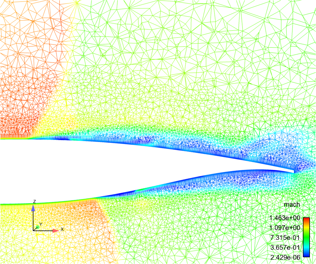
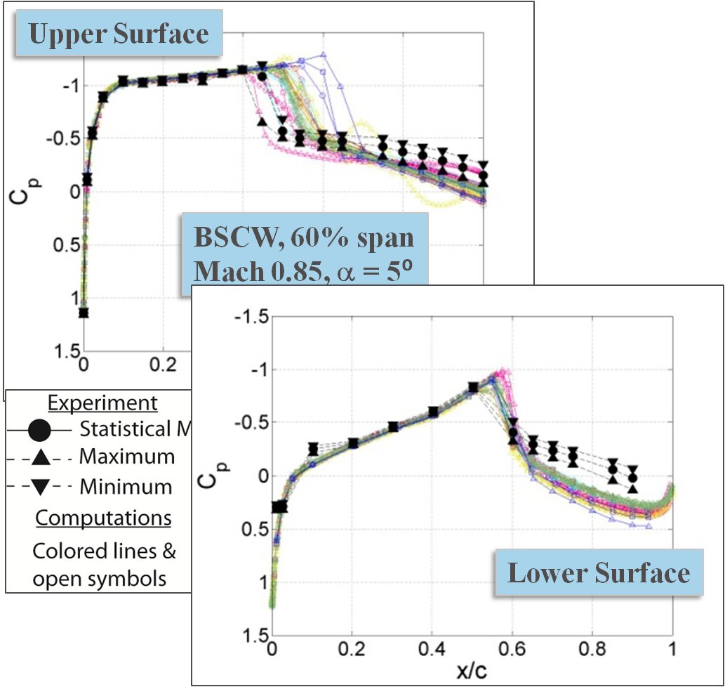
The Benchmark Supercritical Wing (BSCW) was chosen as the configuration for the workshop. The model has geometric simplicity, and the test conditions are such that the flow field has demonstrated complexities. The test conditions for the workshop have been chosen to capture increasing complexities. The flow conditions used for AePW-1 were challenging. Shock-induced separated flow dominates the upper surface and the aft portion of the lower surface at the Mach 0.85, 5° angle of attack cases that were simulated. Separation assessment was performed on the experimental data for the OTT test. Using these results as a guide, cases just outside of the separated flow regime will be emphasized for AePW-2. Steady and forced oscillation analyses will be conducted at Mach 0.7, 3° angle of attack; unforced (steady) and flutter analyses will be conducted at Mach 0.74, 0° angle of attack. An optional case, Case 3, will be re-analysis of the AePW-1 case (Mach 0.85, 5° angle of attack), encouraging the application of higher fidelity tools and detailing spatial and temporal convergence issues.
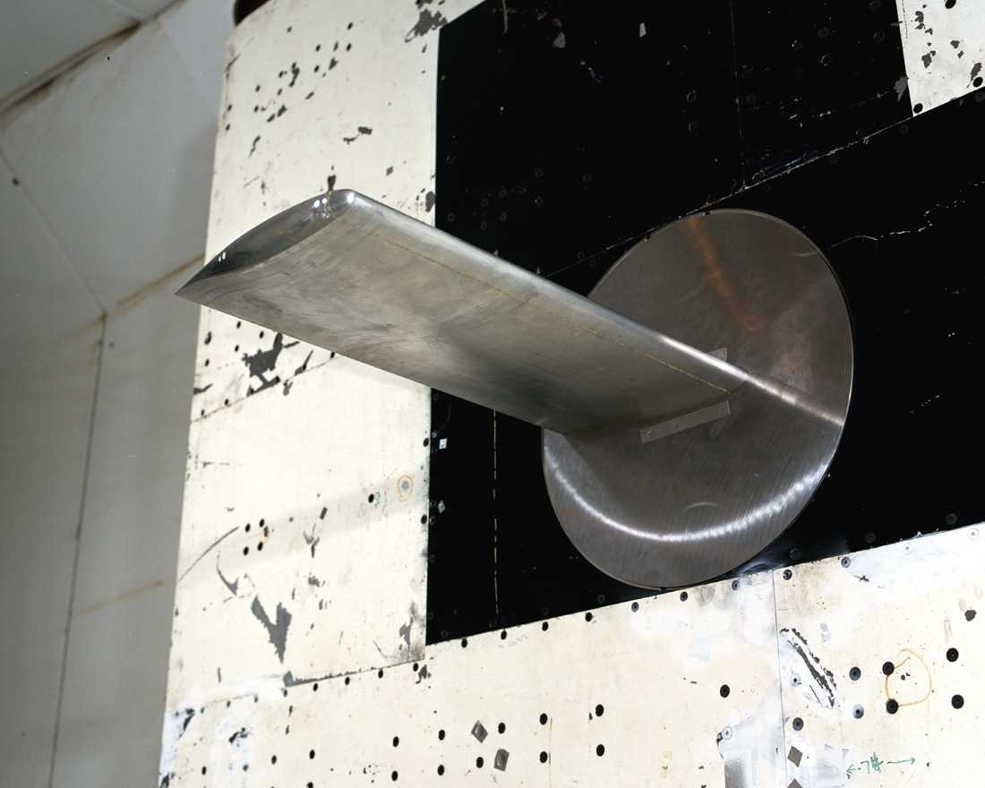
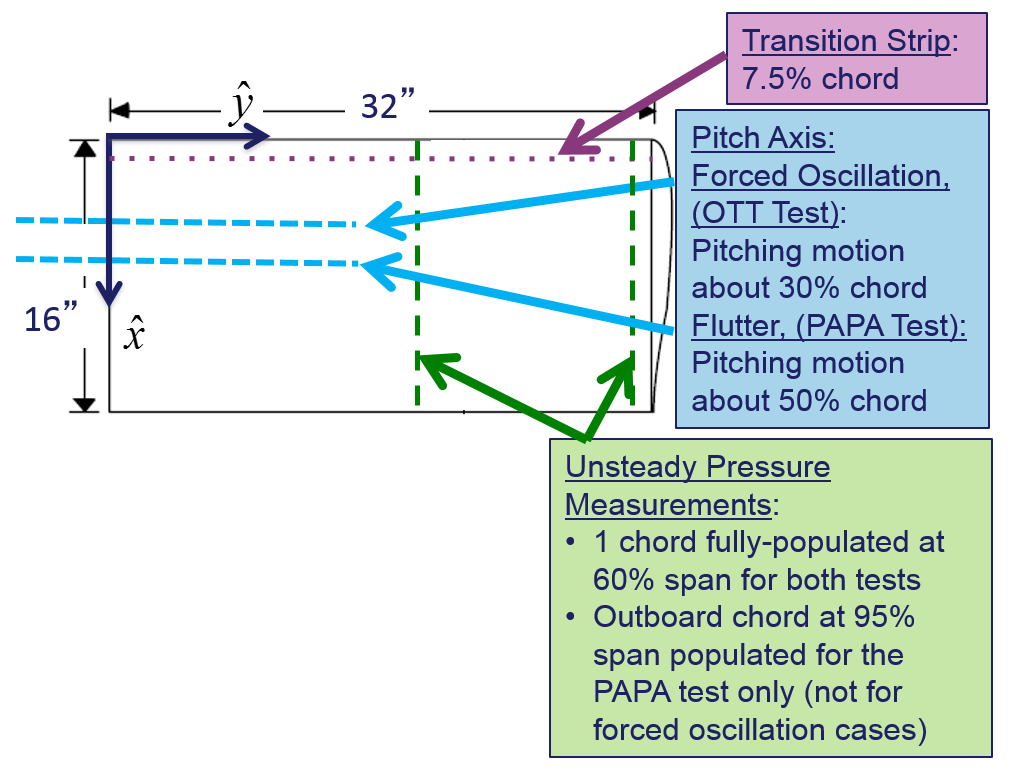
Wind Tunnel Model: The Benchmark SuperCritical Wing (BSCW) was tested in the NASA Langley Transonic Dynamics Tunnel (TDT) in two test entries. The most recent test served as the basis for AePW-1; testing was performed on the oscillating turntable (OTT) which provided forced pitch oscillation data. A prior test was performed on a flexible mount system, denoted the pitch and plunge apparatus (PAPA). Aeroelastic testing was performed for the model on the PAPA, where the mount system provides low-frequency flexible modes that emulate a plunge mode and a pitch mode. The PAPA data consists of steady data and unsteady data at flutter points. Data from both tests will be utilized for comparison with simulation data in AePW-2.
The BSCW airfoil is a NASA SC(2)-0414. The airfoil designation indicates that it was part of the 2nd generation of designed supercritical airfoils, with a design normal force coefficient of 0.4 and a 14% thickness to chord ratio. The planform is rectangular with a wing tip cap shaped as a tip of revolution. The PAPA test was conducted with several flow transition strip configurations; only data using the 35 grit will be used for these comparisons. For the OTT test, the boundary layer transition was fixed at 7.5% chord using size 30 grit. All cases has transition grit on both the upper and lower wing surfaces.
The wing was designed with the goal of being rigid; the spanwise first bending mode of the wing itself has a frequency of 24.1 Hz. The flexible modes that will be modeled in the current effort are provided through the flexible mount system.
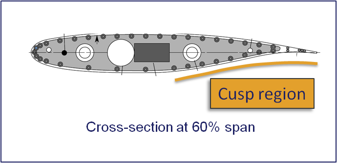
The models instrumentation consists of chord-wise rows of in-situ unsteady pressure transducers; for the PAPA test, there were populated rows at the 60% and 95% span stations. For the OTT test, the 95% span station row was not populated with transducers.
Previous Computations and Results Summary The BSCW case served as a semi-blind test case for AePW-1. There were very small plot of some of the data previously published, but in insufficient detail to be truly useful to the analysis teams. Eight teams performed analyses of the BSCW; they used Reynolds-Averaged Navier-Stokes flow solvers exercised assuming that the wing had a rigid structure. Both steady-state and forced oscillation computations were performed by each team, with some teams choosing to perform time-accurate simulations even for the unforced system case. The results of these calculations were compared with each other and with the experimental data. The steady-state results from the computations capture many of the flow features of a classical supercritical airfoil pressure distribution. The most dominant feature of the oscillatory results is the upper surface shock dynamics. Substantial variations were observed among the computational solutions as well as differences relative to the experimental data. Follow-on studies have included hybrid RANS-LES simulations.
Publications and Presentations
BSCW summary presentation from the AePW-1
OTT testing of the BSCW, by Piatak and Cleckner
NASA_TM4457_BSCW.pdf Includes the physical properties of BSCW (includes measured coordinates in tables)
Testing of the BSCW splitter plate
NASA_TM104180_BMP.pdf Benchmark Models Program description and highlights
AIAA-1992-2368_Dansberry.pdf Includes description of the dynamic characteristics of the BSCW
AePW-1 BSCW Workshop presentations
RUAG_BSCWBSCW_Schuster
BSCW_Mavriplis
BSCW_MSmith
BSCW_ANSYS
BSCW_CHwalowski