High Speed Working Group
Lead: Kirk Brouwer
Objectives
- Assess state of the art coupled FSI tools (coupled: structural dynamics + unsteady aerodynamics) in a predictive manner for high speed applications involving shock-wave boundary-layer interactions (SBLI)
- Develop guidelines and metrics for coupling frequency to characterize degree of non-linear interaction
- Define degree of SBLI and structural dynamic characteristics that require different analysis methods, model fidelity, grid resolution and treatment, temporal resolution, etc.
- Identify gaps in current high-speed FSI experiments to provide feedback for future experiments to get better agreement between test and analysis
Background
- High speed vehicles encounter complex flow physics, including turbulent fluctuations within the boundary layer, SBLI, and intense three-dimensionality that produce extreme aerodynamic loading conditions that directly impact the structure.
- High-speed conditions are particularly challenging for computational tools because the coupling between the extreme environmental loads associated with high-speed flows and nonlinear structures drives unanticipated responses that are path-dependent and evolve over long durations
- Closing the design loop for reusable high-speed vehicles requires a more accurate prediction of the environments and structural response to reduce conservatism
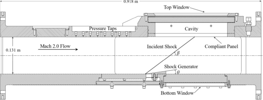
AFRL/SSC RC-19 Clamped Thin Panel
- Representative of metallic skin panel for reusable hypersonic vehicle
-
No SBLI and attached SBLI generated by 4° wedge
- No shock impingement: Periodic post-flutter response (baseline)
- No shock impingement: Chaotic post-flutter response (optional)
- Attached SBLI (4° wedge): periodic response (optional)
-
Conditions:Mach 1.92 ± 0.02 (air)
- T0 = 295.95 ± 2.25 K
- P0 = 345.92 ± 1.12 kPa
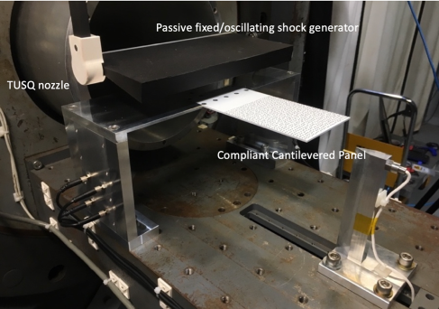
UNSW HyMAX Cantilever Plate
- Representative of a control surface on a high-speed vehicle
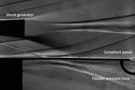
- Shock impingement on 2 mm thin aluminum panel, 130 x 80 mm cantilevered from rigid forebody
-
Fixed wedge angles (2 and 10°)
- 2 degree case is laminar (mandatory)
- 10 degree case is transitional (optional)
- Oscillating wedge (optional)
-
Conditions: Mach = 5.8 ± 0.06 (air)
- T0 = 580 ± 30 K, P0 ± 40 kPa
- Tw = 300 ± 2 K
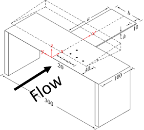
AFRL/SSC RC-19 Clamped Thin Panel Configuration
UNSW HyMAX Configuration
Structural response is 1st mode-dominated
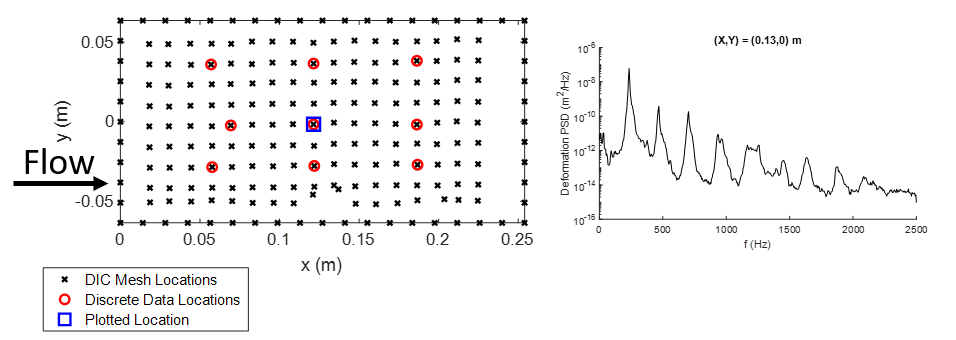
Key Metrics
- Post-processed DIC displacement
- Power spectral density and oscillation amplitude at selected locations
HyMAX Aero Data
- PSP -> surface pressure
- SBLI location and footprint (size and location of separation bubble).
- Pressure transducer time history near the trailing edge for validation.
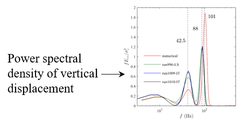
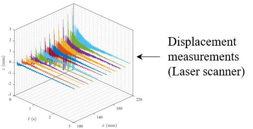
Structural Response Data
- Oscillation/time history of the cantilever plate.
- Schlieren -> image tracking for vertical displacement.
- Laser line scanner -> 100 points along the centerline of the plate.