Geodesy (Datum) Models
Flat Earth
The simplest way to model the Earth's surface is to model it as a plane with constant gravity. Such a system uses either runway-aligned coordinates or a three-dimensional coordinate system in the North-East-Down orientation. Further approximations can be made but generally lead to errors in line-of-sight calculations and high-speed flight. An example of these approximations is integrating the translational rates of the vehicle's positions, which are spherical coordinates, as if they were across a flat surface.
Spheroidal Earth
The spheroidal Earth is a more complicated geodesy model that assumes the Earth is a perfect sphere. A common gravitational model for this spherical Earth is the inverse-square law. The radius of the sphere is chosen to have a surface area that also matches that of the WGS-84 ellipsoidal Earth. With this assumption, all points on the surface are equidistant from the center of the Earth. 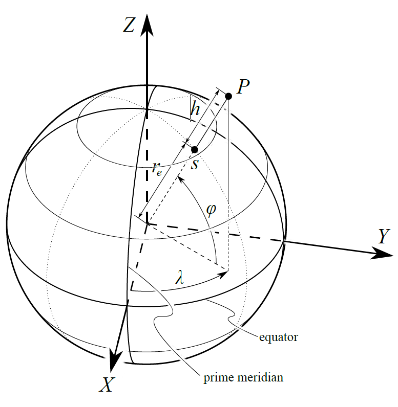
Ellipsoidal Earth (WGS-84)
The World Geodetic System (1984) is an ellipsoidal Earth model that is the standard for cartography, geodesy, and navigation. It uses a standard ellipsoidal reference frame for raw altitude data and a gravitational equipotential surface that defines the nominal sea level. A source of complexity in this model is due to the elliptical shape of the meridians and the ellipsoid's eccentricity, which account for the Earth's geometric flattening at the poles and the bulging at the equator. All orbital check-cases use this geodesy model. 
Coordinate Systems
Body-Axis System
The body-axis system is a common coordinate convention, used for both aircraft and spacecraft. This convention orients the x-axis forward along the body of the vehicle, the z-axis pointing down, and the y-axis pointing out the right side of the vehicle, completing the right-hand rule. For most atmospheric vehicle models, this is a straightforward system. Vehicle subsystems tend to follow this same coordinate system but geometric properties are often defined in a vehicle reference frame. This alternate system has its origin located off the vehicle and the x and z axes are reversed in direction.
Local Reference Coordinates (LRC)
The LRC system uses a fixed location on Earth and references its orientation to that fixed point. A common reference point for the LRC system is a runway. In this case, the origin of the runway is usually located at a threshold with the xrwy axis aligned with the centerline and points down the runway. The yrwy axis is to the right of the centerline and either an hrwy axis pointing up or a zrwy pointing into the ground. Another common reference point for the LRC system has its origin directly beneath the body/vehicle on the surface of the Earth and is oriented North, East, and Down which is known as the NED frame.
Local Horizontal Local Vertical (LVLH)
It is useful to describe a vehicle's attitude for guidance, navigation and control by means of standard Euler angles (roll, pitch and yaw) with respect to the LVLH coordinate system. The Z-axis is defined to be a unit vector pointing from the vehicle's center of mass to the celestial body's center of mass. The Y-axis is a unit vector that is normal to the orbit plane, pointing in the opposite direction to the instantaneous orbit angular momentum vector. Lastly, the X-axis completes the standard right-handed coordinate frame based on the Y and Z axes. 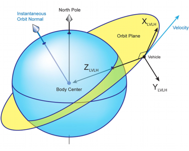
Earth-Centered (ECI and ECEF)
The Earth-Centered Inertial (ECI) system is an inertial reference frame that uses the center of the Earth as the origin, and is commonly used for state propagation of atmospheric and orbital simulations. Positions in the ECI system are typically rectilinear coordinates such as X, Y, and Z. The X-axis points from the center of the Earth to the intersection of the Equator and Prime Meridian. The Z-axis points from the center of the Earth to the North pole. The Y-axis is the cross product between the X and Z axes. The ECI system is not truly an inertial system because the origin moves with the Earth as it revolves around the sun. This "inertial" feature is vital to 6DOF systems because propagation in a rotating frame is complex. To compute other environmental effects, the Earth-Centered Earth-Fixed (ECEF) system can be used relative to the ECI system.
Atmospheric scenarios assume these systems share polar axis of rotation and are related through a single rotation. Sometimes the period of this rotation is assumed to be 24.0 hours, but the WGS-84 standard specifies a mean Earth rotational rate ω = 7,292,115.0e-11 rad/s corresponding to the "inertial" or sidereal period of 23.9345 hours (slightly less than a day, since the Earth is orbiting around the sun: the Earth rotates approximately 361 degrees in a solar day between local noons). 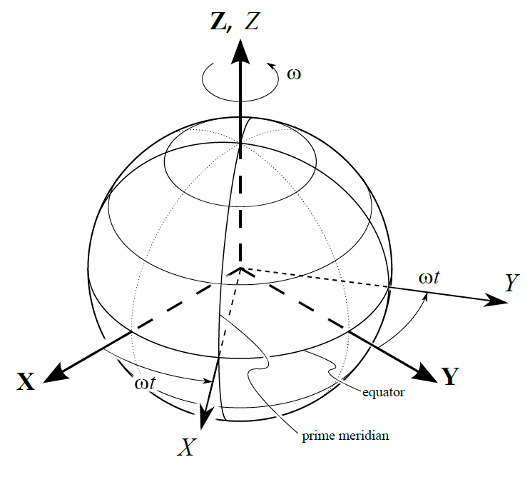 Orbital scenarios use the ECI system, known as J2000, which is modeled on an equatorial system at the epoch of noon on 1 January 2000 in Greenwich, England. The ECI and ECEF systems used here were established by the International Earth Rotation and Reference System Service (IERS) which publishes code and tabular data that can be used to compute X, Y and Z in J2000 coordinates. This includes the rotation-nutation-precession (RNP) matrix M, which transforms from ECI to ECEF.