High Speed Working Group
Lead: Eric Blades
High Speed October 2023 Meeting Slides
High Speed October 2023 Slides
Hymax Update
RC-19 Compliant Panel Analysis
High Speed December 2022 Slides
High Speed November 2022 Slides
High Speed October 2022 Slides
High Speed September 2022 Slides
High Speed August 2022 Slides
High Speed July 2022 Slides
High Speed June 2022 Slides
High Speed May 2022 Slides
High Speed March 2022 Slides
High Speed February 2022 Slides
High Speed January 2022 Slides
High Speed December 2021 Slides
Objectives
- Assess state of the art coupled FSI tools (coupled: structural dynamics + unsteady aerodynamics) in a predictive manner for high speed applications involving shock-wave boundary-layer interactions (SBLI)
- Develop guidelines and metrics for coupling frequency to characterize degree of non-linear interaction
- Define degree of SBLI and structural dynamic characteristics that require different analysis methods, model fidelity, grid resolution and treatment, temporal resolution, etc.
- Identify gaps in current high-speed FSI experiments to provide feedback for future experiments to get better agreement between test and analysis
Background
- High speed vehicles encounter complex flow physics, including turbulent fluctuations within the boundary layer, SBLI, and intense three-dimensionality that produce extreme aerodynamic loading conditions that directly impact the structure.
- High-speed conditions are particularly challenging for computational tools because the coupling between the extreme environmental loads associated with high-speed flows and nonlinear structures drives unanticipated responses that are path-dependent and evolve over long durations
- Closing the design loop for reusable high-speed vehicles requires a more accurate prediction of the environments and structural response to reduce conservatism
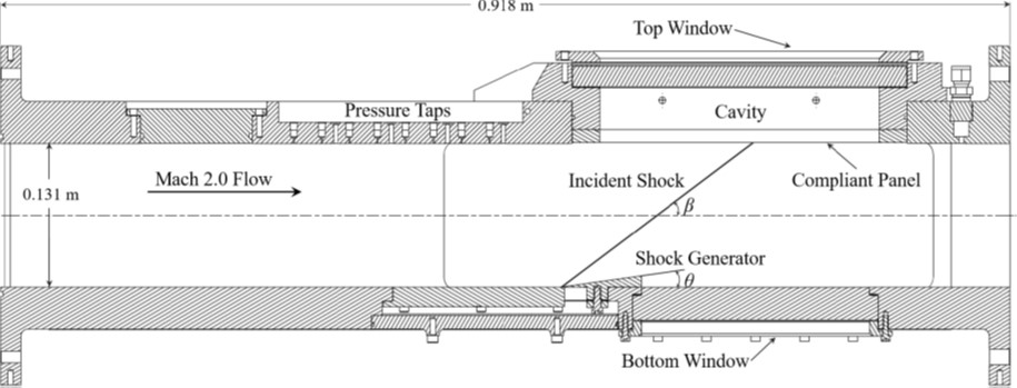
AFRL/SSC RC-19 Clamped Thin Panel
- Representative of metallic skin panel for reusable hypersonic vehicle
-
No SBLI and attached SBLI generated by 4° wedge
- No shock impingement: Periodic post-flutter response (baseline)
- No shock impingement: Chaotic post-flutter response (optional)
- Attached SBLI (4° wedge): periodic response (optional)
-
Conditions:Mach 1.92 ± 0.02 (air)
- T0 = 295.95 ± 2.25 K
- P0 = 345.92 ± 1.12 kPa
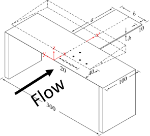
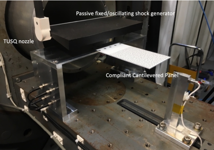
UNSW HyMAX Cantilever Plate
- Representative of a control surface on a high-speed vehicle
- Shock impingement on 2 mm thin aluminum panel, 130 x 80 mm cantilevered from rigid forebody
-
Fixed wedge angles (2 and 10°)
- 2 degree case is laminar (mandatory)
- 10 degree case is transitional (optional)
- Oscillating wedge (optional)
-
Conditions: Mach = 5.8 ± 0.06 (air)
- T0 = 580 ± 30 K, P0 ± 40 kPa
- Tw = 300 ± 2 K
AFRL/SSC RC-19 Clamped Thin Panel Configuration
UNSW HyMAX Configuration
Structural response is 1st mode-dominated
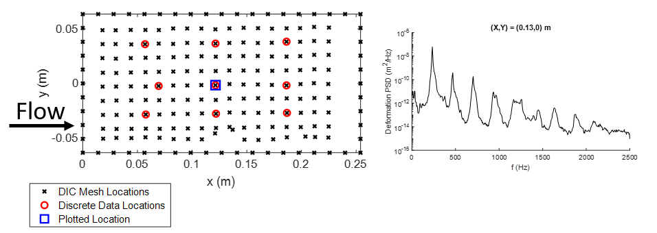
Key Metrics
- Post-processed DIC displacement
- Power spectral density and oscillation amplitude at selected locations
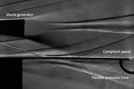
HyMAX Aero Data
- PSP -> surface pressure
- SBLI location and footprint (size and location of separation bubble).
- Pressure transducer time history near the trailing edge for validation.

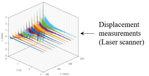
Structural Response Data
- Oscillation/time history of the cantilever plate.
- Schlieren -> image tracking for vertical displacement.
- Laser line scanner -> 100 points along the centerline of the plate.